A small project showing how to adapt a cheap NES controller clone to use with a ZX Spectrum/Didaktik as a Kempston compatible joystick.
This project came to be because I have decided to repair my old Didaktik M computer (1992 vintage). It is the first computer I have owned so it has a bit special place in my heart.
While I have managed to repair both the Didaktik and its power supply and even built a new keyboard for it that doesn’t drive me crazy (Didaktik M had a horrible keyboard and mine is also very worn from a lot of use back in the 90s), I don’t have any joysticks for it to play games with.
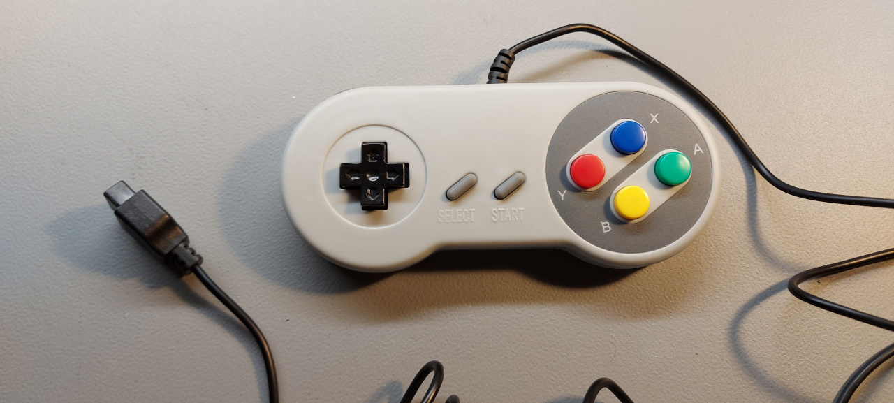
A cheap “Atari style” joystick would work, however those things are notoriously fragile and not very good for the style of games these machines had. A gamepad would be better. So a cheap clone of a NES controller has been procured.

Figure 1: (S)NES controller
The problem
The assumption was that given that this has a 9 pin D-Sub connector, it is most likely only a “dumb” gamepad where the buttons are directly wired to the controller – as in the common Atari-style joysticks.
Alas, no – this is a weird clone of a SNES controller using the normal NES serial protocol with a non-standard connector. The extra buttons (X, Y, shoulder buttons) are simply duplicating the function of the A,B buttons, with some pulsing, possibly some kind of “auto-fire” mode.
Apparently, this is meant to be used with the “Famiclones” – bootleg copies of the Nintendo NES/Famicon console. The pinout is not difficult to figure out but it is also available online.

Figure 2: Pinout (from here)
However, there is no reason why a standard NES controller wouldn’t work here as well but the proprietary Nintendo connector would need to be replaced.
Interface
Spectrum obviously can’t handle NES controllers without a bit of extra help, so a simple Kempston compatible interface has been designed, using a Xilinx XC9536XL CPLD1.
These ICs are plenty fast for the slow Z80 bus, are relatively cheap and can replace all the address decoding logic, data latching, clock division and serial protocol handling needed to convert the NES controller to an Atari-style “dumb” joystick.
And the most important feature – these chips are one of the few ICs for programmable logic that are still in production and are 5V tolerant.
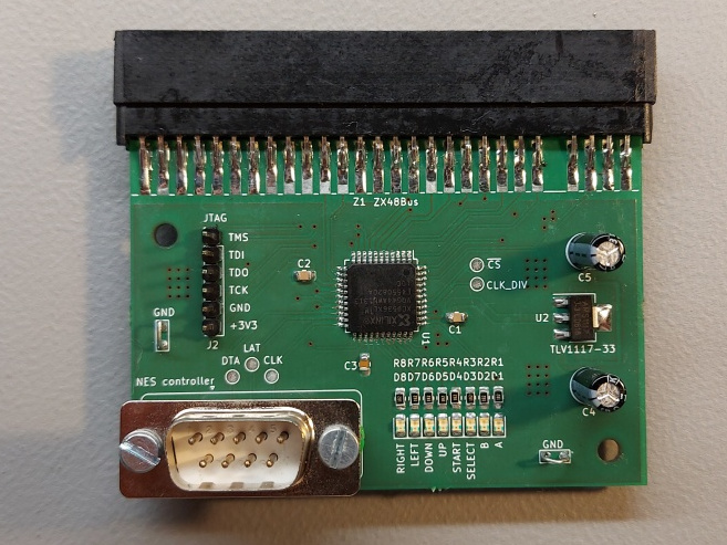
The interface contains only the CPLD, 3.3V voltage regulator, connectors and 8 LEDs indicating the state of the controller buttons. Those are, strictly speaking, not required but I have found them useful for debugging. The CPLD has a lot of pins, so why not use them.

Figure 4: Finished interface (top)

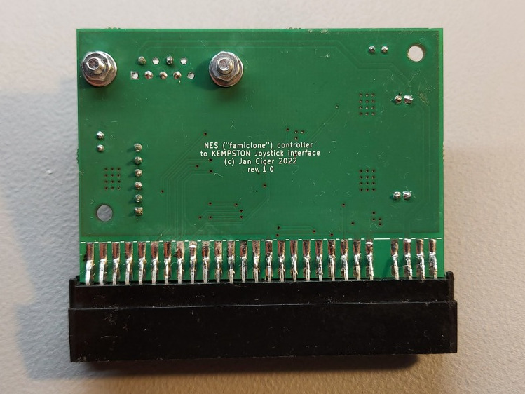
Figure 5: Finished interface (bottom)
The firmware for the CPLD has 4 main functions:
- Decoding the address bus and the Z80 control signals (/IORQ, /RD) to identify the access to the port 0x31 used by the Kempston joysticks.
- Divide the system clock (~4MHz) down to 512kHz for the controller. While the shift registers used in these should be able to run much faster, it is not needed and the slower frequency will also limit the EMI radiated by the controller cables.
- Implement a state machine that latches the state of the controller and serially reads it into an 8bit internal register. This is double buffered, so when the Spectrum reads the port, the data will always be stable. The content of the buffer is also output to the 8 LEDs to indicate which controller buttons are pressed.
- Remap the data inside the internal register to the Kempston joystick format – both A and B buttons act as fire, the D-pad acts as joystick directions.
Sourcing ZX Spectrum bus connectors
The original ZX Spectrum card edge connectors are long out of production but it is possible to DIY one rather easily. Some people cut these connectors from a wider connector.
However, I have been lucky to find an AliExpress seller that sells both the 2x28pin connector that the Spectrum bus uses and also the unusual 2x6pin ones that the Didaktik M uses for joysticks instead of the standard 9pin D-Sub ones.
Link (no affiliation): https://www.aliexpress.com/item/1005003003362076.html

Figure 6: Original connector (front)

Figure 7: Original connector (top)

Figure 8: Detail of the installed connector
These connectors are slightly too wide and won’t fit into the Didaktik. However, that is easy to fix – the plastic protrusions on the sides need to be sanded down by about 1-1.5mm so that they are flat.
The slots for the PCB need to be cut as well. I have used a small endmill and milled them out in my drill press but a saw would likely work as well.
The key is made out of a piece of thin FR4 (PCB) material, cut to size and glued in place with a drop of superglue.
PCBs
I have two extra boards left, if someone is interested feel free to contact me.
Downloads
- KiCad 6.x project
-
CPLD bitstream files (JEDEC + SVF, they are identical).
Use a JTAG interface, such as the Bus Blaster from Dangerous Prototypes to program the CPLD. I have used the xc3sprog utility, otherwise UrJTAG works as well. There is, of course, the Xilinx IMPACT tool (part of ISE) as well.
Footnotes:
Dangerous Prototypes has a good introduction to these: Xilinx XC9500XL CPLD Quick Start
